Design
Documentation

Analysis & Design

Part 1

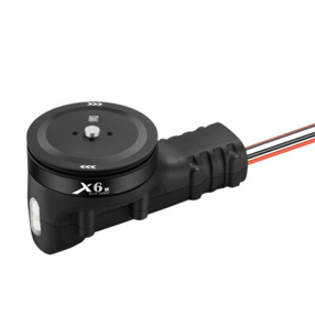
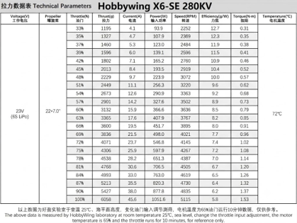
The unmanned aerial vehicle (UAV) platform is designed in a quadcopter configuration to support a 7.3 kg empty weight and a maximum payload capacity of 5 kg. The propulsion optimization was calculated in SolidWorks so that the total take-off weight — comprising the airframe, battery, and maximum mission payload — is sustained at the 50% throttle (hover) level, and the motor efficiency band is kept at the maximum thrust-to-energy ratio.

A stacked airframe architecture was developed to damp the disturbing effects of the high-mass energy block (6S 30,000 mAh) and variable mission payloads on flight dynamics. In this configuration, the lower layer is allocated to the SIYI A8 Mini gimbal and payload-release systems, where field of view is critical; the middle layer to the high-current Power Distribution Board (PDB) and cable harnesses; and the upper layer to the low-interference-tolerance flight-control and communication avionics.

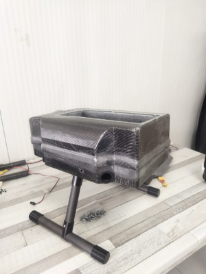
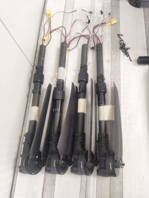
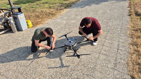
The battery block is positioned at the volumetric center of the airframe to minimize Center of Gravity (CG) deviations that directly affect autonomous cruise stability, and it is fed from a dedicated carbon fiber housing (top-accessible) with electromagnetic and thermal insulation. To shorten setup time during field deployment and reduce transport volume, carbon fiber tube-type foldable motor arms and quick-release landing gear mechanisms were integrated into the system. The rigidity of the entire system was validated through SolidWorks Finite Element Analysis (FEA) processes.
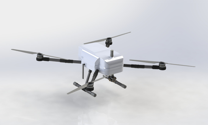
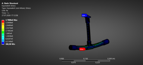
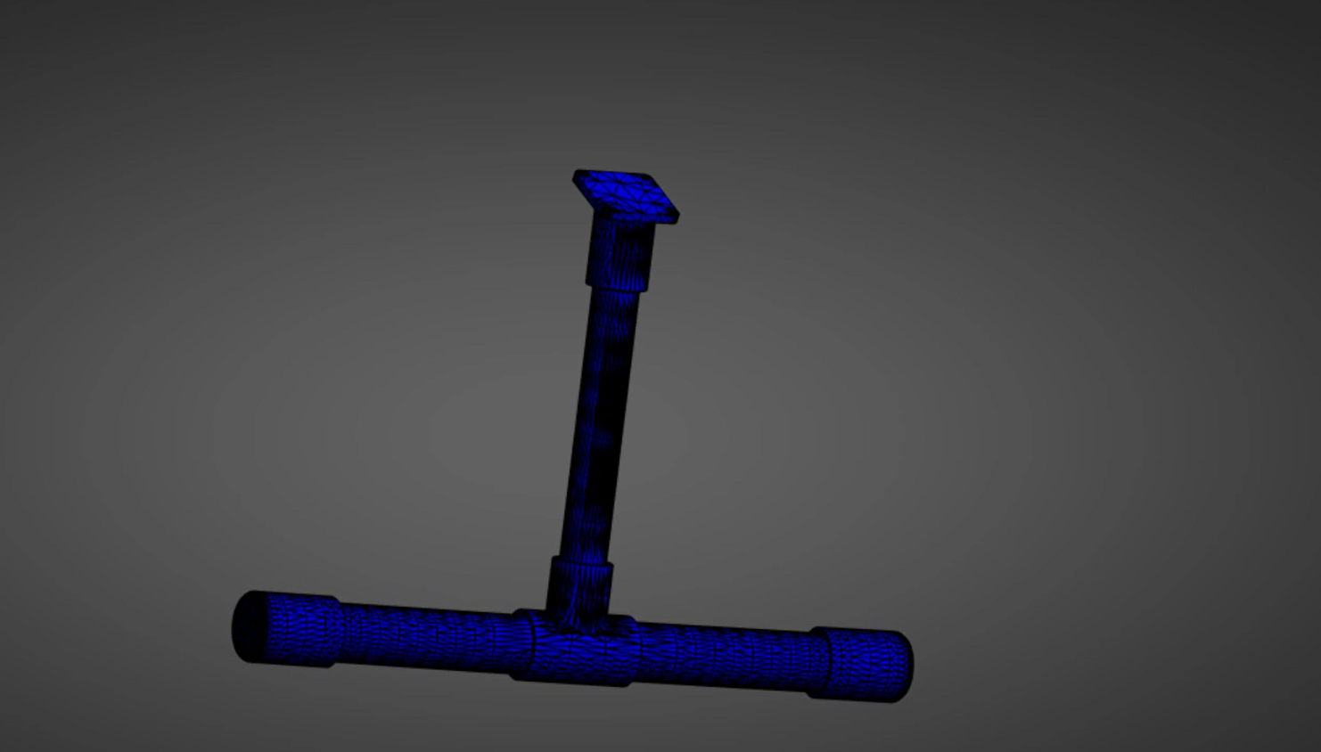
Quadcopter Stacked Airframe CG Optimization SolidWorks FEA
Structural Manufacturing & Composite Processing

Part 1

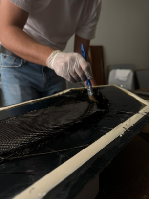
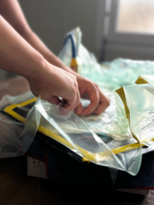
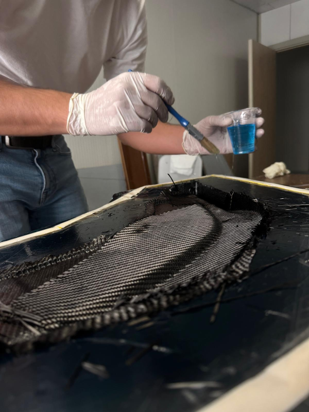
The platform's load-bearing internal chassis and outer aerodynamic shell are manufactured entirely from carbon fiber composite using the vacuum bagging technique over custom-made moulds. Through the vacuuming process, the resin-to-fiber ratio is optimized, eliminating the material's microscopic voids and producing a homogeneous composite matrix.

The carbon fiber layup is laid in orientations that maximize structural rigidity against the dynamic loads generated by the propulsion system and the torsional and shear forces that occur during maneuvers; the joints where stress concentration peaks are reinforced with laminated fiberglass weaves. At the motor-arm and landing-gear connections, which are exposed to thermal fatigue and high-cycle dynamic (cyclic) loading, aviation-grade machined metal joints are preferred over 3D-printed polymers (PLA, etc.) that carry a risk of structural deformation.

The volumetric weight saving achieved on the non-load-bearing aerodynamic fairing elements keeps the total system mass below the limit values, directly enabling the aircraft to reach a 48-minute flight endurance at a maximum cruise speed of 8 m/s.


Carbon Fiber Vacuum Bagging Composite Layup Machined Joints

Ground Control Station

Software

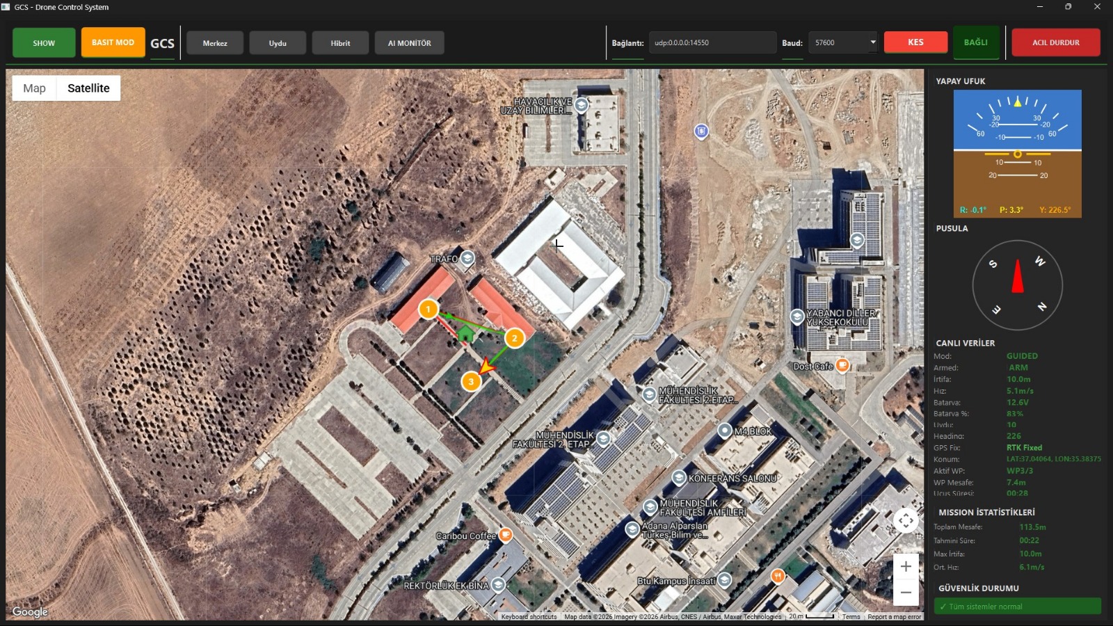
The Ground Control Station (GCS) is a Python-based mission management interface that provides real-time communication with the UAV through the telemetry network. During flight, it continuously displays critical flight data, including GPS position, altitude, airspeed, battery status, and mission progress. The interface also visualizes detected targets on an interactive map, allowing the operator to review each candidate based on its location, classification, and confidence score. Once a target is selected, the corresponding GPS coordinates are transmitted back to the UAV, enabling autonomous payload delivery. This architecture ensures efficient mission monitoring, operator interaction, and reliable command execution throughout the flight.


Python Telemetry Interactive Map Ground Control Station interface

Object Detection & Payload Delivery

Software

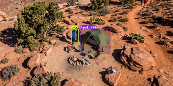
The object detection system runs on the NVIDIA Jetson Nano and performs real-time image processing using a custom-trained YOLO model. Images captured by the SIYI A8 Mini gimbal camera are continuously analyzed to identify mission targets. For each detection, the UAV's GPS coordinates, altitude, and gimbal orientation are combined with camera calibration parameters to estimate the target's real-world location. Multiple detections of the same object are clustered to improve localization accuracy and eliminate duplicate targets. Candidate targets are ranked according to detection frequency and confidence score before being presented to the Ground Control Station. After the operator selects the desired target, the UAV autonomously navigates to the specified location and activates the Arduino-based payload release mechanism, ensuring a safe and reliable delivery process.


Jetson Nano YOLO Geolocation Payload Release Object detection on aerial imagery

Mapping

Software

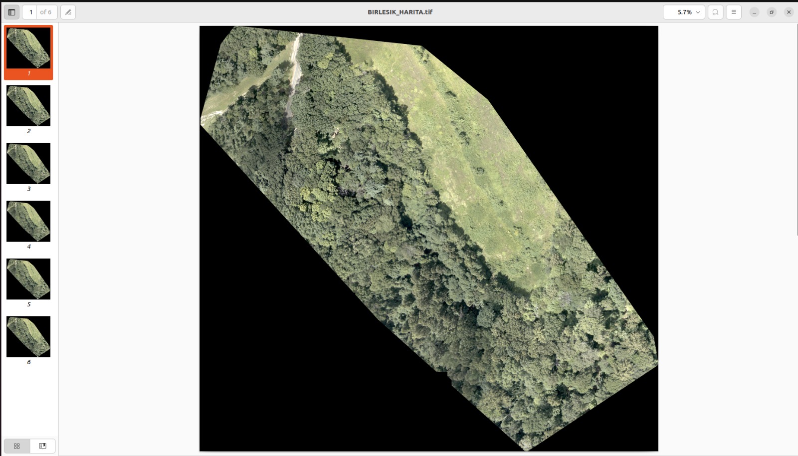
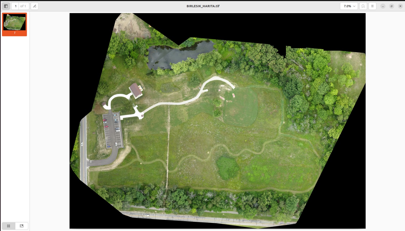
The mapping module operates independently from the object detection pipeline, allowing both tasks to run simultaneously without reducing system performance. Instead of capturing images at fixed time intervals, photographs are acquired based on the distance traveled by the UAV to maintain consistent image overlap and improve mapping quality. Each image is tagged with GPS coordinates and camera orientation before being transmitted to the Ground Control Station. During the mission, a low-latency preview map provides the operator with immediate situational awareness. After the flight, all collected images are processed offline to generate a high-resolution orthomosaic map, ensuring both rapid mission feedback and accurate final mapping results.


Orthomosaic Distance-Based Capture Offline Processing
Mapping preview Generated orthomosaic map

Avionics & Hardware Architecture

Part 1

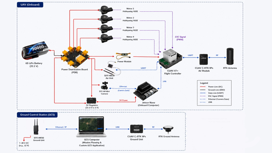
The avionics infrastructure is configured around the requirements of uninterrupted data transmission and a distributed processing architecture within a 30 km operational range. Real-time target detection (tents, people, etc.) is provided through low-latency, YOLO-based edge-AI algorithms running on NVIDIA Jetson Nano hardware and supported by parallel GPU processing; the targeting data is integrated directly with the SIYI A8 Mini gimbal system. Sub-centimeter positioning and orthomosaic mapping data are provided through the CUAV CRTK 9PS system.

Propulsion-system communication is established over the CAN bus protocol, which has a high tolerance to electromagnetic interference (EMI); RPM, ESC temperature, and operating-frequency data are relayed to the flight controller in real time with closed-loop system logic. While the system's telemetry and digital video link to the GCS (Ground Control Station) is carried over the SIYI HM30 network, the Radiolink AT9S (12-channel) command receiver is routed directly to the HM30 module using the RCIN line, raising the manual-intervention range to the 30 km specification.

As an EMI isolation strategy, the RTK antennas and RF receivers are placed at the highest point of the airframe, isolated from the high-current buses; and the main distribution lines (PDB) fed from the 6S 30,000 mAh energy unit are separated from the signal cables with electrical radiation shielding.


Jetson Nano YOLO Edge-AI CAN Bus RTK GNSS SIYI HM30