From Preparation to Mission Output: End-to-End Flow
How flight planning, target search, mapping, operator approval, and payload delivery join one mission chain.
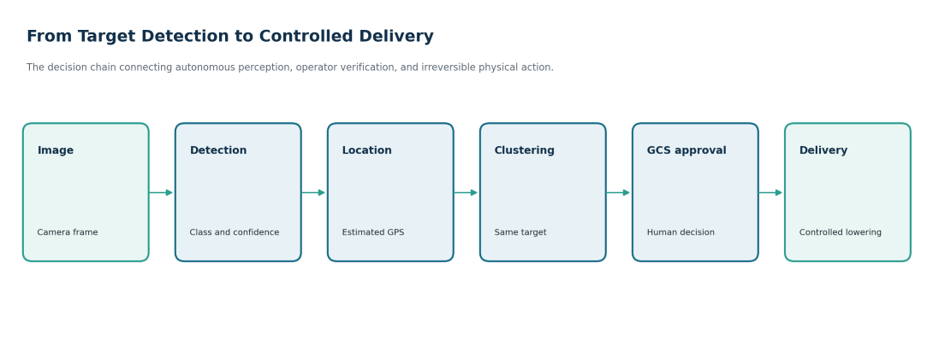
Operating a system's components individually is an important development step, but the real challenge of the competition mission is making those components work together in the correct order and within a shared time limit. Camera imagery feeding target detection, detection results reaching the GCS, operator approval returning to the aircraft, and the map product being generated after the mission form one connected data and decision chain.
Why divide the mission into stages?
Each stage produces the conditions required by the next. During preparation, telemetry, GPS, battery, and the mission plan are checked. The waypoint mission verifies that the aircraft follows the expected route. During search, images are analyzed for targets while the mapping pipeline collects the required frames. Delivery begins only after the operator approves a target candidate.
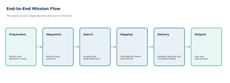
Figure 1. High-level end-to-end mission flow from preparation to the creation of mission outputs.
Interfaces between stages
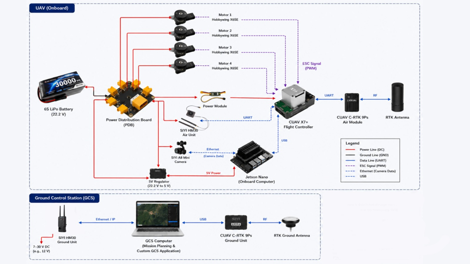
Integration problems often appear not inside one algorithm, but at the boundary between two components. Examples include a target candidate produced by Jetson reaching the GCS with the correct timestamp, an operator-approved coordinate corresponding to the intended target, and the flight controller applying the delivery position safely.
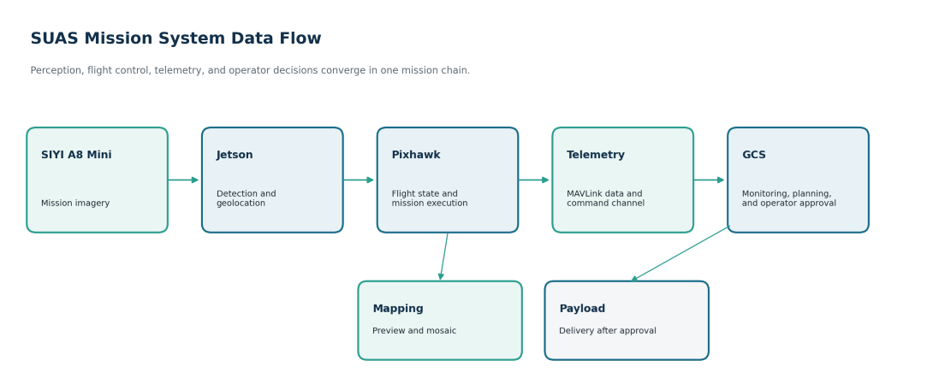
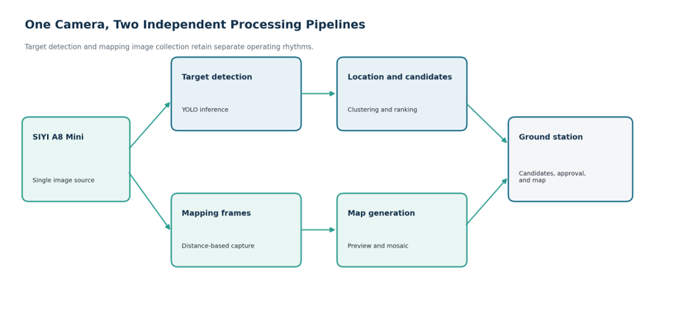
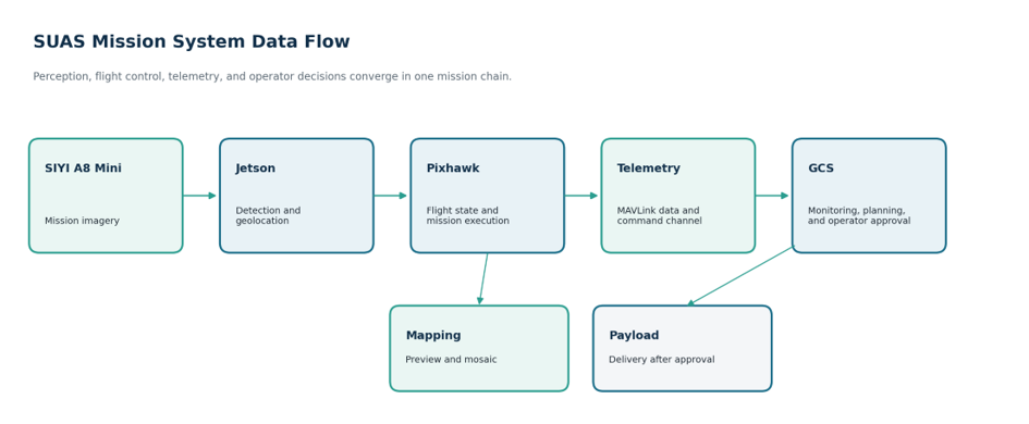
Figure 2. During the end-to-end mission, data moves in both directions between the airborne unit and the ground station.
Integration tests should therefore answer more than “Was a target found?” or “Did the aircraft reach the waypoint?” The record must also show when data was generated, which component received it, what the operator saw, and which approval triggered the physical action.
The role of human decisions in the mission
Autonomy does not mean removing the operator from the entire mission. Repetitive tasks such as route following and continuous target search can run onboard. Final selection remains with the operator because a delivery to the wrong target cannot be reversed. At this point, the GCS converts information produced by the autonomous system into a form the operator can evaluate.
What should a successful end-to-end test demonstrate?
| Stage | Essential output to validate |
|---|---|
| Preparation | Connection, GPS, battery, geofence, and mission plan satisfy safe starting conditions |
| Flight | The waypoint mission is executed in the expected order and within defined limits |
| Perception | A target candidate is created with image, class, confidence, and estimated location |
| Approval | The operator's selection returns to the aircraft with the correct candidate and coordinates |
| Delivery | The aircraft holds safely over the target and the controlled release mechanism operates |
| Mapping | A map is generated from real-flight imagery with measurable quality and processing time |
Current status and the next technical milestone
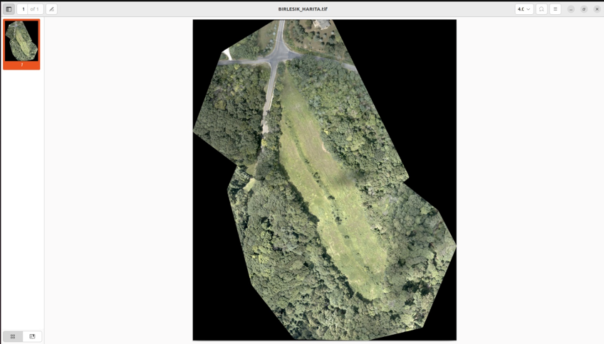
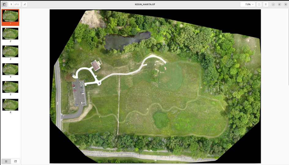
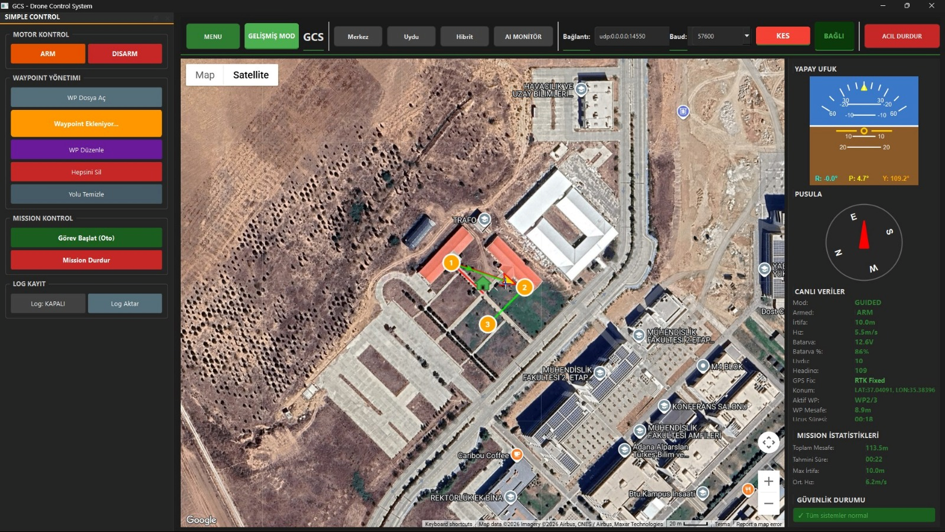
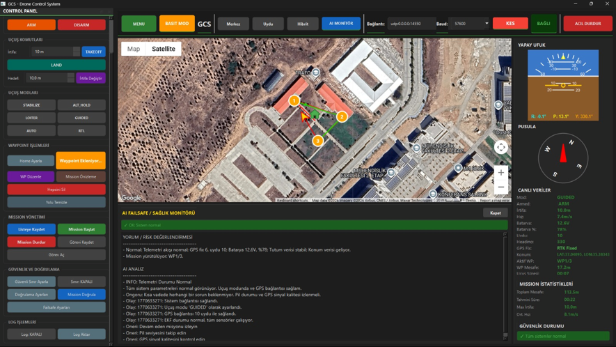
The GCS mission-planning, telemetry, safety, and logging functions can be shown through screenshots. Data-set examples are available for target detection, and TIFF mosaics generated on a computer from a data set are available for mapping. Payload delivery and a complete end-to-end mission in which all components finish together during the same real flight are not yet presented as validated outputs.
The next technical milestone is to test candidate selection, coordinate transmission, navigation to the target, controlled delivery, and map generation from real-flight imagery within one mission. When processing times, command and approval timestamps, position errors, failsafe events, and map-quality measurements are retained in one logging structure, the system will not only have operated; its operation will also be demonstrable.